How to Build a Time-Lapse Controller to Photograph Growing Plants

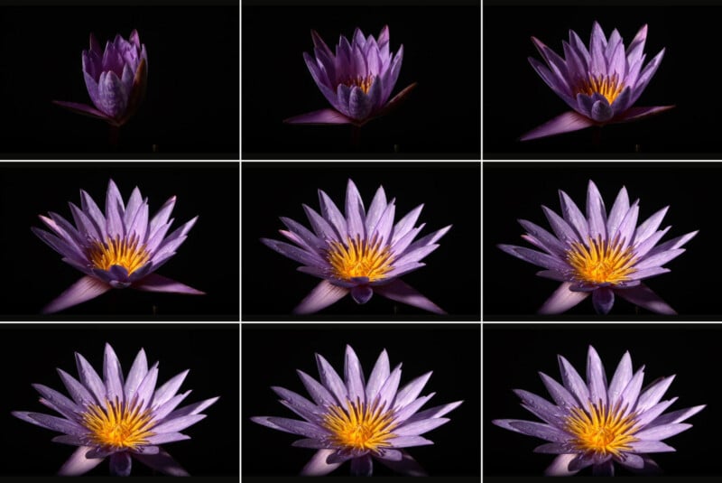
This article is about how to make a time-lapse system that controls the lighting conditions and triggers the camera shutter for time-lapse plants.
Time-lapse photography is an area of photography where images are taken every few minutes – here to capture the motion of growing plants. I have been using these techniques for over 30 years. First running 16 mm Bolex cameras before graduating to 35 mm Mitchel cameras and eventually digital cameras. For each camera system, I had to build dedicated time-lapse controllers. Each camera system had its own unique challenges to overcome. Problems of stability of exposures over long durations are now solved with highly stable rolling shutters. The stability of light sources is not an issue with modern LED lights.
The reason to make these relatively complex time-lapse systems is to control three things – the camera shutter, the grow lights for the plants, and the photo light for the exposure. To grow plants over long periods of time requires a grow light that stays on for 12 to 18 hours a day. The typical exposure cycle involves the grow light turning off, the photo light turning on and the camera taking an exposure, then the photo light turns off and the grow light turns back on.
The use of modern LED lights greatly simplifies the process.
Time-lapse control systems are used by so few people that there is currently no manufacturer of this equipment so the few people that photograph in this area typically make their own equipment. Although it is common for cameras to have built-in intervalometers (time-lapse controllers) the cameras cannot control grow lights or photo lights.
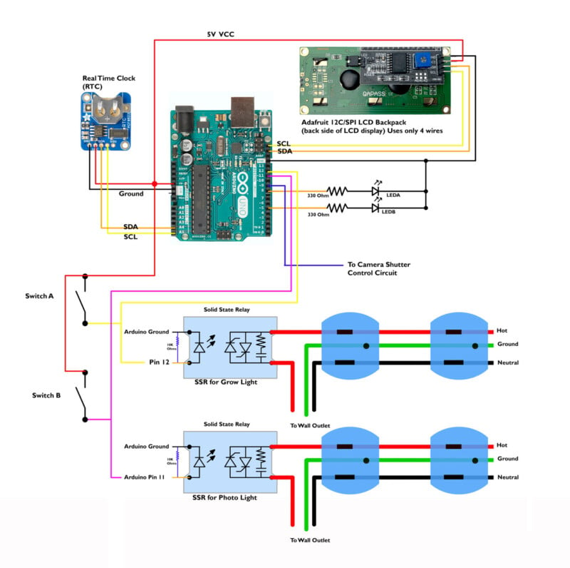
The Arduino code here uses a Real Time Clock (RTC) that keeps track of the time of day for a few years until the internal battery runs out. The RTC circuit uses special Arduino code to set the clock time.
The process for setting the RTC is quite simple and well described on the Adafruit website that manufactures the RTC.
The real time clock allows the grow light to turn on at a specific time and turn off at a set time.
I run the plant grow light from 2 am to 8 pm which is an on time of 18 hours which is quite common for plants in the growing phase of their life. This time can be changed to simulate fall or spring sunlight.
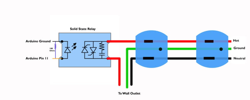
The Arduino controller turns off the grow light before each exposure and turns on a photo light. To control these large voltages and currents a special device is used – a solid state relay (SSR) is used. The SSR is an electronic switching device that switches on or off when an external voltage of 5 volts is applied across its control terminals. The SSR serves the same function as an electromechanical relay, but solid-state electronics contain no moving parts, have a longer operational lifetime, and are much faster than a mechanical relay. For this controller, I used a CRYDOM 120v 10A Solid State Relay. Many similar units are widely available on the internet and the critical part is that the SSR can be controlled with the 5-volt output from the Arduino. The control pins in this circuit (pin 11 and Pin 12) have a 10kilo ohm pull-down resistor attached to the pins. This resistor allows any residual voltage to flow to ground and keeps the SSR control pins in the correct logic state. On is +5 volts while off is zero volts.

There are also two manual switches (switch A and Switch B) attached to the SSR which allow the relays to be manually controlled. This allows the photo light to be turned on to allow for focus and exposure settings, the second manual switch turns on the grow light to make sure it is operating correctly. I mounted the SSR units to blocks of aluminum to help with cooling. Even after running for many hours, the SSR stayed cool.
There are also two LED lights attached to pins 5 and 8 which show the state of the controller.
Data about the current state of the photo shoot is displayed on the Adafruit 12C/SPI LCD Backpack – this is a modified LCD display that is quite easy to use and only requires 4 wires to run. This is a big improvement over the old displays that took over 10 pins to run. Like several of the other components here, this screen is also available from Adafruit.com
If you decide to wire up this circuit make sure you know what you are doing. The SSR handles wall current that will give you a serious shock if you wire wrong or put your fingers in the wrong place.

The finished circuit was placed in a plastic box mainly to keep wires in place.
My photo light of choice is the Godox SL60W which uses a 60-watt daylight-balanced LED with an internal cooling fan. This is an incredibly well-built light that has no measurable variation in brightness. The grow light can be any grow light that you like, over the years I have gone through a number of them but currently use a 1200-watt unit suspended about two feet above the plants.
/*
Time-LapsePlants2024advanced-V2.ino
Ted Kinsman [email protected]June 2024 update
- includes LCD display
-timer to show next event
-exposure (EXP=) counter
Turns on and off a SSR (Solid State Relay) on pin 12 (grow Light)
Turns on and off a SSR (Solid State Relay) on pin 11 photo LED light
A camera on pin 9.
Test LED on pin 8
NOTE: the ON cycle of the grow light needs to be between 0 hours and 24 hours.
it cannot cross midnight – this issue is due to math dealing with the reset
of the clock at midnight
*/
//initialize the liquid crystal library
//the first parameter is the I2C address
//the second parameter is how many rows are on your screen
//the third parameter is how many columns are on your screen
#include
#include
#include
#include
RTClib myRTC; //name the real time clock for the code
LiquidCrystal_I2C lcd(0x27,20,4); // set the LCD address to 0x27 for a 16 chars and 2 line display
// constants won’t change. Used here to set a pin number:
const int GrowLightOn = 2; //(6AM) turn Grow light on in 24 hour time
const int GrowLightOff = 20; // (6pm)turn Grow light off at 18:00 in 24 hour time
const int LEDB = 5; //test LED
const int GrowLight = 11; // the number of the grow light on pin 11 pin
const int PhotoLight = 12; // Photo light on pin 12
const int Camera = 9; // Pin 9 controls the camera shutter
const int LEDA = 8; //Test LED to show the camera shutter is running on pin 8
long int n = 0; //counter for keeping track of the number of exposures
long int K = 0; //counter for keeping track of the seconds to next exposures
int CameraShutter = 100; //time the camera shutter is pulsed to trigger on in milliseconds
long int PhotoWaitTimeSEC = 180; //time between camera exposures in Seconds
long int PhotoWaitTimeMillSec = 0; // a variable to track milliseconds for wait time
long int ExposureTimeSEC = 1; //exposure in seconds (time to keep photo light on for)
int PhotoLightOn= 1000; //Maybe use this variable ???time to keep photo light on //for.
void setup() { //line below is only run once as setup
lcd.init(); // initialize the lcd
// Print a message to the LCD.
lcd.backlight();
Serial.begin(9600); //turn on serial com interface
Wire.begin(); // the Arduino is ready to send and receive data over the I2C bus.
// this command is used to send data to the LCD display
pinMode(GrowLight, OUTPUT); //GrowLight is an output for Solid state relay
pinMode(PhotoLight, OUTPUT); //PhotoLight is an output for Solid state relay
pinMode(Camera, OUTPUT); //Camera controls the camera shutter and is also an output
pinMode(LEDA, OUTPUT); //test led A is an output to show if the shutter has been triggered (pin 8)
pinMode(LEDB, OUTPUT); //test led B is an output to show if system is waiting (pin 5)
PhotoWaitTimeMillSec = PhotoWaitTimeSEC*1000;
//changes wait time from seconds to milliseconds
ExposureTimeSEC = ExposureTimeSEC*1000; //convert from seconds to milliseconds
delay (1000); // wait for all the electronics to warm up.
}
void loop() {
digitalWrite (GrowLight, HIGH); //turn on grow light
K = PhotoWaitTimeSEC; // counter to record seconds on LCD screen
DateTime now = myRTC.now();
//send the following info to the serial port
Serial.print(“PhotoWaitTimeSEC = “);
Serial.print(PhotoWaitTimeSEC);
Serial.println (” msec”);
Serial.print(“ExposureTimeSEC = “);
Serial.print(ExposureTimeSEC);
Serial.println (” msec”);
Serial.print(“Current Time = “);
Serial.print(now.hour(), DEC);
Serial.print(‘:’);
Serial.print(now.minute(), DEC);
Serial.print(‘:’);
Serial.print(now.second(), DEC);
Serial.println();
//code below controls the grow light by a solid state relay controlled by pin 11
if((now.hour() >=GrowLightOn) && (now.hour() <=GrowLightOff)){ //turns grow light on digitalWrite (GrowLight, HIGH); //NOTE: the ON cycle needs to be between 0 hours and 24 hours.it cannot cross midnight //this issue is due to math dealing with the reset of the clock at midnight } else { digitalWrite (GrowLight, LOW); } Serial.print(“Waiting for next exposure “); Serial.println(); //below is sequence to trigger a picture digitalWrite (GrowLight, LOW); //turn off grow light digitalWrite (LEDB, LOW); //system red LED turns off to show wait time between shots is over digitalWrite (PhotoLight, HIGH); //turn on photo light Serial.print(“Grow light is off, photo light is on”); Serial.println(); delay (3000); //let photo light stabilize for 3 seconds digitalWrite (Camera, HIGH); digitalWrite (LEDA, HIGH); Serial.print(“Camera has been triggered “); Serial.println(); delay (CameraShutter); // make a trigger pulse for the camera digitalWrite (Camera, LOW); Serial.print(“Taking the exposure “); Serial.println(); delay (ExposureTimeSEC); //keep all the lights constant for the exposure time digitalWrite (LEDA, LOW); delay (1000); //keep the photo light on for one second -this is required if the exposure time above is set incorrectly digitalWrite (PhotoLight, LOW); //turns off photo light at the end of the exposure sequence //the daily cycle of the grow light will be controlled at higher level logic Serial.print(“Photo Number = “); Serial.println(n); digitalWrite (LEDB, HIGH); //turn on red LED to show the system is waiting n=n+1; //the variable n is the exposure counter //the lines below will send the seconds to next exposure to the LED //also, this is the wait delay for the next exposure while (K > 0){
//lcd.setCursor(1,11);
//lcd.clear();
lcd.setCursor(0,0);
lcd.print(“Wait=”);
lcd.print(PhotoWaitTimeSEC);
lcd.print(” Sec.”);
lcd.setCursor(0,1);
lcd.print(” “); //one way to clear values from bottom line
lcd.setCursor(0,1);
lcd.print(“EXP=”);
lcd.print (n); //send image number to LCD screen
lcd.print(” NXT=”);
lcd.print (K); //send time sec to next image to LCD screen
delay(1000);
K=(K-1);
}
}

Time-lapse plant photography is never a sure thing. Even after all these years, I calculate only one out of three sequences turns out the way I want. Practice, practice, practice is the key to success.
The design can be simplified by using electrical outlet boxes mounted directly to the controller. Future systems will have the wait time and grow lights adjusted from the controller.
I hope you enjoyed this little article and decide to explore the world of time-lapse plant photography for yourself.
There are not very many books on time-lapse plant photography, but John Ott’s book My Ivory Cellar: The Story of Time-Lapse Photography by Twentieth Century Press 1958 is quite good and changed the direction of my photography as a young man.


Source link

